
Wire Size and Terminal Block Selection in mm² and AWG
Choose a terminal block for the conductor you will actually terminate: its copper cross-sectional area, solid or stranded construction, end preparation and number of wires at the connection. A matching nominal size is the beginning of that decision. The finished conductor end must also fit the permitted connection geometry.
For buyers moving between metric and AWG drawings, two questions often get mixed together: what area does the wire have, and which wire configurations does this terminal accept? A conversion table answers the first. The terminal’s connection data answers the second.
Separate area conversion from common size pairings
AWG numbers and metric nominal sizes are different series. For example, 14 AWG has a nominal area of about 2.08 mm². It is not exactly 2.5 mm², even when catalogues place those sizes alongside one another as familiar purchasing classes.
| AWG | Approximate nominal area in mm² |
|---|---|
| 20 | 0.52 |
| 18 | 0.82 |
| 16 | 1.31 |
| 14 | 2.08 |
| 12 | 3.31 |
| 10 | 5.26 |
Source: Electronic Theatre Controls cable size conversion table. These are area references, not terminal current ratings or permission to substitute one cable size for another.
If a drawing specifies 2.5 mm² and an available cable is marked 14 AWG, record the difference. Check the cable requirement and the terminal’s separately declared AWG range before accepting a substitution. An approximate metric pairing cannot establish the cable’s ampacity or the terminal’s approval for that wire.
Read the complete connection entry
Antong’s product tables use more than one way to describe conductor capacity. The following entries illustrate why their headings matter.
| Model | Catalogue conductor entry | What the entry tells you |
|---|---|---|
| SP004-01 | 2.5–4.0 mm² | The listed wire range for this terminal-strip model |
| SP014-01 and SP015-01 | 2 × 6 mm² | A conductor-count and size configuration that must be interpreted with the connection drawing |
| SP037/UKK80A input | 1 × 6–16 mm² | The input has its own connection range |
| SP037/UKK80A outputs | 4 × 2.5–6 mm² plus 2 × 2.5–16 mm² | The six output positions comprise two different size groups |
Sources: SP004 terminal strips, SP014/SP015 connectors, and SP037 UKK distribution blocks.
As a first check, a 10 mm² output conductor is outside the listed 2.5–6 mm² group on UKK80A but within the listed 2.5–16 mm² group. The installer still needs the physical position map to identify the correct opening. Do not select an output by appearance or assume all openings share the input’s range.
Likewise, a single value such as 2 × 6 mm² does not establish a minimum conductor size or automatically approve a twin ferrule. Request the arrangement for the actual conductor construction and end preparation.
Check the conductor end as well as the copper area
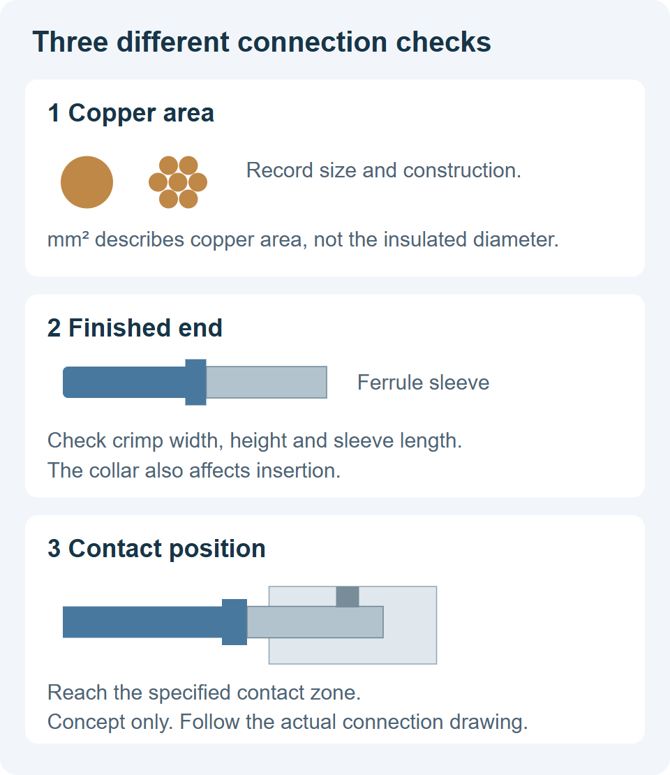
A bare solid conductor, a flexible strand bundle and a crimped ferrule with the same nominal copper area do not present identical shapes to a clamp. A ferrule adds a metal sleeve; its crimp profile and insulating collar can affect insertion.
WAGO’s guidance on ferrules explains that a sleeve or collar can reduce the maximum size accommodated by its connectors and that ferrule length must suit the connection’s strip-length requirement. The practical lesson is to look for connection data that distinguishes bare and ferruled conductors, rather than carrying the bare-wire maximum over unchanged.
Conceptual inspection guide. The drawings do not represent a particular Antong clamp or prescribe an insertion length.
For a ferruled conductor, the useful dimensions are the finished crimp’s width and height, the conductive sleeve length and the collar position. The sleeve must reach the intended contact zone without the collar stopping insertion early. A loose or oversized crimp cannot be corrected by simply tightening the terminal harder.
Distinguish two wires from two connection positions
There are three different arrangements to consider:
One conductor in each of two separate clamping positions.
Two bare conductors held by one clamping unit.
Two conductors crimped into one twin ferrule and inserted into an approved clamping unit.
Permission for one arrangement does not establish permission for the others. Nor does adding the two copper areas describe the outside geometry of their finished ends.
A useful example of explicit connection data is the Phoenix Contact UT 35 product table. It lists separate ranges for one flexible conductor, a ferruled conductor and two conductors, including a twin-ferrule option. Those ranges belong to that product. They illustrate the information to request for an Antong connection; they are not substitute limits for an Antong model.
When a product lists 2 × 6 mm², keep that notation intact in the enquiry. Ask which entry points and clamps it refers to, which conductor classes are covered, and whether the proposed ferrule arrangement is included. A larger-looking opening is not evidence of multi-wire approval.
Use a short acceptance checklist
Before releasing a conductor and terminal combination, record each item below for the exact production parts.
| Check | Record to keep |
|---|---|
| Cable identity | Manufacturer, part number, copper size and solid or stranded construction |
| Connection position | Input or output, physical position and number of conductors at each clamp |
| End preparation | Bare wire or exact ferrule type, sleeve length and crimp tooling |
| Allowed range | The product data covering this conductor construction and termination |
| Assembly | Specified strip length and tightening torque where applicable |
| Finished sample | Full insertion, collar clearance, captured strands and the required inspection result |
For example, an enquiry for SP014-01 should state “two 6 mm² flexible copper conductors” and identify the proposed ferrules if used. It should then ask Antong to confirm the connection arrangement, permitted termination, strip length and torque. That gives the supplier something concrete to assess without treating the catalogue shorthand as a complete installation instruction.
Questions buyers commonly encounter
Can I fit a smaller wire into a terminal with a larger maximum size
Only when the smaller wire is within the stated range for its construction and termination. A maximum value alone does not establish the minimum size the clamp can hold.
Does a ferrule always improve the connection
A suitable ferrule can make strand handling more consistent. It must still be compatible with the terminal, conductor and crimping method. Use the connection method specified for that combination.
Does matching the wire size also confirm the current rating
No. Check the cable and terminal electrical limits separately. The SP004 table, for example, lists conductor ranges and current ratings as separate fields. Selecting by wire size alone leaves the load check unfinished.
For quotations, send the cable specification and intended connection arrangement with the exact terminal model. This is more useful than requesting a generic “2.5 mm² terminal” and deciding the wire preparation after the parts arrive.